Máy cân bằng laser LAX 600 (tia đỏ) và LAX 600G (tia xanh) là công cụ hiện đại được thiết kế để hỗ trợ trong các công việc đo đạc, căn chỉnh chính xác. Sản phẩm phù hợp với các công trường xây dựng và đảm bảo độ bền cao.

1. Lắp pin và bật máy
Sử dụng pin Li-ion CAS 12 V (2 Ah hoặc 4 Ah). Đẩy pin vào theo hướng mũi tên cho đến khi khớp vào vị trí. Đảm bảo pin đã được sạc đầy trước lần sử dụng đầu tiên. Không sạc lại pin đã đầy hoặc để pin xả hoàn toàn. Để bật máy, sử dụng công tắc trượt. Máy sẽ tự động khởi động ở chế độ cân bằng ngang. Đèn LED màu xanh lục cho biết máy đang hoạt động.
2. Chức năng laser
- Chọn chế độ laser: Nhấn nút "Tia laser" để thay đổi các chế độ laser. Luôn có ít nhất một tia laser hoạt động. Tất cả tia laser chỉ có thể tắt bằng công tắc trượt hoặc nút "Manual" trong chế độ thủ công.
- Chế độ thủ công: Kích hoạt chế độ này bằng công tắc "Manual". Trong chế độ này, tia laser nhấp nháy hai lần mỗi 5 giây, không sử dụng chức năng tự cân bằng. Phù hợp cho các công việc đánh dấu và căn chỉnh.
3. Sử dụng bộ thu laser
Khi làm việc ở khoảng cách xa, kích hoạt chế độ xung. Bộ thu phải tương thích với laser dạng xung và phù hợp với màu tia laser.
4. Kiểm tra độ chính xác
- Phương đứng: Tạo đường tham chiếu, căn chỉnh máy cách 2 m, so sánh tia laser với đường tham chiếu. Sai lệch không vượt quá 1 mm.
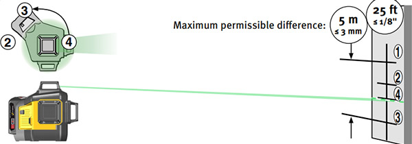
- Phương ngang: Đặt máy cách tường ít nhất 5 m, xoay 90° và kiểm tra bốn điểm tham chiếu. Sai lệch không vượt quá 6 mm ở khoảng cách 10 m.
- Kiểm tra góc: Đánh dấu các điểm tham chiếu (A, B, C, D, E), đảm bảo khoảng cách từ A đến B, B đến C, và B đến D bằng nhau. Sai lệch từ A đến E cần được đo để đảm bảo độ chính xác.
5. Thông số kỹ thuật
Máy có độ chính xác ±0.3 mm/m, hoạt động trong nhiệt độ từ -10°C đến +40°C. Thời gian sử dụng pin: LAX 600 lên đến 28 giờ và LAX 600G lên đến 15 giờ.
6. Bảo quản và lưu ý
Không sử dụng thiết bị trong điều kiện quá nhiệt độ bảo quản từ -20°C đến +63°C. Thường xuyên kiểm tra độ chính xác để đảm bảo hiệu quả. Đọc kỹ hướng dẫn sử dụng và tuân thủ các quy định an toàn khi vận hành.
LAX 600 và LAX 600G mang lại sự chính xác và tiện lợi, đáp ứng các yêu cầu khắt khe trong xây dựng và căn chỉnh.
Mục đích sử dụng
Chúc mừng bạn đã sở hữu dụng cụ đo STABILA.
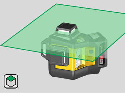
Các dòng máy cân bằng laser STABILA LAX 600 được thiết kế dễ dàng sử dụng, với ba tia laser 360° phục vụ việc cân bằng theo phương ngang và phương dọc, tạo góc 90° và xác định đường dọi đứng.
Thiết bị laser này được trang bị vỏ bọc kín (theo tiêu chuẩn IP 65) phù hợp sử dụng trong các công trường xây dựng. Máy có khả năng tự cân bằng trong phạm vi ±4°.
Các tia laser được thiết kế theo chế độ xung, cho phép làm việc ở khoảng cách xa hơn khi sử dụng kết hợp với bộ thu tia laser chuyên dụng của STABILA. Để biết thêm thông tin, vui lòng tham khảo hướng dẫn sử dụng đi kèm bộ thu tia.
Dòng sản phẩm LAX 600 chỉ hoạt động với pin 12 V Li-Ion thuộc Hệ thống CAS.
LAX 600 G:
Bộ thu phải phù hợp với tia laser màu xanh lá.
Hướng dẫn sử dụng này áp dụng cho tất cả các thiết bị thuộc dòng LAX 600.
Tia laser của thiết bị chỉ hiển thị một màu duy nhất.
Nếu bạn vẫn còn thắc mắc sau khi đọc hướng dẫn sử dụng, bạn có thể gọi điện để được tư vấn bất cứ lúc nào: 096 779 3398.
Tính năng và chức năng:
- Tia laser chế độ xung
- 1 tia laser 360° theo phương ngang
- 2 tia laser 360° theo phương dọc
- Góc 90° theo phương ngang và phương dọc
- Chức năng tia laser dọi đứng
- Chế độ thủ công
- Ren gắn chân máy 1/4"
- Hộp đựng đi kèm
- Hệ thống STABILA CAS – Pin Li-Power 12 V 2.0 Ah (không có sẵn trong tất cả các bộ)
- Bộ sạc SC 30, 12-18 V, hệ thống CAS (không có sẵn trong tất cả các bộ)
LAX 600 G: Bao gồm tia laser màu xanh lá để cải thiện khả năng nhìn bằng mắt thường.
2.1 Hướng dẫn an toàn cho thiết bị laser
Đối với các thiết bị laser thuộc Class 2, mắt bạn thường được bảo vệ khỏi việc tiếp xúc ngắn hạn với tia laser nhờ phản xạ tự nhiên của mí mắt đóng lại và/hoặc phản xạ quay đầu. Nếu tia laser chiếu vào mắt, hãy nhắm mắt lại ngay và xoay đầu ra khỏi đường đi của tia. Không nhìn trực tiếp vào tia laser hoặc tia phản xạ.
Kính laser STABILA dành cho thiết bị của chúng tôi không phải là kính bảo hộ an toàn; chức năng của nó chỉ là tăng cường khả năng nhìn thấy tia laser.
- Không chiếu tia laser trực tiếp vào người khác!
- Tránh làm lóa mắt người khác bằng thiết bị!
- Giữ thiết bị ngoài tầm với của trẻ em!
- Việc sử dụng các thiết bị điều chỉnh hoặc vận hành không được nêu rõ trong tài liệu này, hoặc sử dụng thiết bị không đúng cách, có thể dẫn đến việc tiếp xúc nguy hiểm với bức xạ!
2.2 Hướng dẫn an toàn cho pin Li-ion
Hãy đọc kỹ hướng dẫn an toàn và hướng dẫn sử dụng dành cho pin Li-ion.
3. Unit components
 |
 |
 |
 |
Bảng thông tin chức năng
Dưới đây là phiên bản Việt hóa của bảng thông tin mà bạn đã cung cấp:
| STT | Mô tả | STT | Mô tả |
|---|---|---|---|
| 1 | Cửa sổ phát tia laser 360° theo phương ngang | 16 | Ren gắn chân máy 1/4" |
| 2 | Cửa sổ phát tia laser 360° theo phương dọc | 17 | Vỏ máy – Bảo vệ chống nước và bụi theo tiêu chuẩn IP 65 |
| 3 | Công tắc trượt: Bật/Tắt với khóa vận chuyển | 18 | SUB 10 |
| 4 | Nút: Tia laser ngang | 19 | Bu lông kết nối 1/4" |
| 5 | Nút: Chế độ thủ công Bật/Tắt | 20 | Lỗ treo |
| 6 | Nút: Tia laser dọc | 21 | Bề mặt nam châm |
| 7 | Đèn LED xanh/đỏ: Trạng thái hoạt động Bật/Tắt, pin | 22 | Ren gắn chân máy 1/4", 5/8" |
| 8 | Đèn LED xanh: Chế độ xung, nhiệt độ hoạt động | 23 | SWB 10 |
| 9 | Nút: Tia laser 90° theo phương dọc | 24 | Lỗ treo |
| 10 | Nút: Chế độ xung dành cho hoạt động thu tia | 25 | Kẹp |
| 11 | Pin | 26 | Công tắc trượt |
| 12 | Nút nhả pin | 27 | Ốc khóa – Điều chỉnh độ cao |
| 13 | Nút đỏ: Kích hoạt hiển thị dung lượng | 28 | Điều chỉnh tinh |
| 14 | Đèn LED xanh: Hiển thị dung lượng pin | 29 | Ốc điều chỉnh để căn chỉnh giá đỡ |
| 15 | Số sê-ri |
4. Commissioning
4.1 Lắp đặt và sạc pin
Chỉ sử dụng pin thuộc Hệ thống CAS 12 V Li-ion (Cordless Alliance System).
Đẩy pin vào theo hướng mũi tên cho đến khi nó khớp vào vị trí. Pin phải có đủ dung lượng sạc. Hãy sạc đầy pin trước lần sử dụng đầu tiên (quan sát hiển thị). Không sạc lại pin đã đầy.
Kiểm tra dung lượng pin: Nhấn nút đỏ. Pin không được cắm vào bộ sạc khi kiểm tra.
Hiển thị LED: dung lượng pin thấp (<20%) – cần sạc pin. Không để pin bị xả hoàn toàn.
Sạc pin:
Hãy đọc kỹ hướng dẫn an toàn và hướng dẫn sử dụng dành cho pin.
Nhả khóa giữ và tháo pin ra khỏi thiết bị laser. Lắp pin vào bộ sạc. Cắm bộ sạc vào ổ cắm điện.
Khi quá trình sạc hoàn tất, bộ sạc sẽ tự động chuyển sang chế độ bảo quản. Pin có thể được để trong bộ sạc.
 |
4.2 Bật máyĐưa máy LAX 600 (tia đỏ) hoặc LAX 600G (tia xanh) vào vị trí làm việc và bật máy bằng công tắc trượt.Máy luôn khởi động ở chế độ cân bằng ngang và tự động cân bằng. Đèn LED màu xanh lục hiển thị trạng thái máy đang hoạt động. |
|
 |
 |
 |
 |
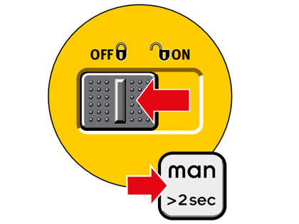 |
4.3 Vận hành không sử dụng chức năng tự cân bằngChế độ đánh dấu chỉ có thể được kích hoạt bằng công tắc "Chế độ thủ công". Trong chế độ này, tia laser sẽ nhấp nháy hai lần mỗi 5 giây.Máy LAX 600 (tia đỏ) hoặc LAX 600G (tia xanh) không ở chế độ tự cân bằng và chỉ có thể được sử dụng trong chế độ này để đánh dấu và căn chỉnh. |
5. Chức năng
5.1 Chọn chức năng laser
Sau khi bật thiết bị bằng công tắc trượt, bạn có thể sử dụng nút "Tia laser" để thiết lập các chức năng laser theo nhu cầu.
Để chỉ báo rằng thiết bị đã được bật và khóa vận chuyển đã được mở, không thể tắt tất cả các tia laser cùng lúc thông qua nút "Tia laser".
Vì vậy, luôn có một tia laser được kích hoạt và hiển thị. Tất cả các tia laser chỉ có thể được tắt thông qua công tắc trượt hoặc nút "man" trong chế độ thủ công.
 |
 |
 |
 |
5.2 Làm việc với bộ thuChế độ xung phải được kích hoạt khi làm việc ở khoảng cách xa hoặc sử dụng bộ thu phù hợp.Lưu ý: Bộ thu cần tương thích với laser dạng xung và phù hợp với màu của tia laser. |
 |
6. LED indicators
 Operation with levelling function Operation with levelling function |
 Operation activated Operation activatedUnit temperature > 60°C / 140°F Ensure the unit is in the operating temperature range |
 Operation without levelling function Operation without levelling function |
 Operation activated Operation activatedBattery check failed Replace the battery pack |
 Operation with levelling function Operation with levelling functionBattery capacity low |
 Operation activated Operation activatedGet in touch with STABILA |
 Operation with levelling function Operation with levelling functionLaser in pulse mode |
 CAS battery CAS batterycharge capacity too low --> Insert battery pack and charge |
 Operation activated Operation activatedBattery temperature < -20°C / -4°F Ensure the unit is in the operating temperature range Check accuracy |
 LED/laser beam lights up constantly LED/laser beam lights up constantly LED/laser beam flashes LED/laser beam flashes LED flashes and changes colour LED flashes and changes colour |
 Operation activated Operation activatedBattery temperature > 70°C / 158°F Ensure the unit is in the operating temperature range Check accuracy |
7. Using the SWB10 bracket
Máy LAX 600 / LAX 600G có thể được gắn và căn chỉnh trên tường hoặc bề mặt bằng cách sử dụng giá đỡ SWB10. Kẹp có thể được dùng để gắn giá đỡ vào các khung chống đứng. Lỗ treo cho phép thiết bị được treo lên đinh hoặc móc.
 |
 |
 |
Gắn và căn chỉnh LAX 600 / LAX 600G
Thiết bị LAX 600 / LAX 600G được gắn vào giá giữ bằng bu lông. Sử dụng bề mặt nam châm, giá giữ có thể được gắn vào tấm trượt trên giá hoặc trực tiếp lên các bề mặt kim loại có từ tính.
Giá giữ cần được căn chỉnh sơ bộ theo chiều dọc bằng cách sử dụng ốc điều chỉnh, đảm bảo LAX 600 / LAX 600G nằm trong phạm vi tự cân bằng.
Sau khi ốc kẹp được nới lỏng, LAX 600 / LAX 600G có thể được di chuyển lên trên tối đa 11 mm (0,4"). Độ cao chính xác sẽ được điều chỉnh bằng nút điều chỉnh tinh.
8. Kiểm tra độ chính xác
LAX 600 / LAX 600G được thiết kế để sử dụng trong các công trường xây dựng và đã được căn chỉnh hoàn hảo trước khi rời khỏi nhà máy. Tuy nhiên, giống như tất cả các thiết bị đo chính xác khác, bạn nên kiểm tra độ chính xác của thiết bị định kỳ.
Hãy luôn kiểm tra thiết bị trước khi bắt đầu làm việc, đặc biệt là khi thiết bị đã chịu tác động mạnh hoặc rung lắc đáng kể.
- Kiểm tra phương đứng (Vertical check)
- Kiểm tra phương ngang (Horizontal check)
- Kiểm tra góc (Angle check)
8.1 Kiểm tra phương đứng
Kiểm tra hai tia laser dọc
- Tạo một đường tham chiếu, ví dụ bằng cách sử dụng dây dọi.
- Đặt và căn chỉnh thiết bị LAX 600 / LAX 600G ở khoảng cách Y trước đường tham chiếu.
- So sánh tia laser với đường tham chiếu.
- Ở khoảng cách 2 m (7'), tia laser không được lệch khỏi đường tham chiếu quá 1 mm (11/256”).
- Thực hiện kiểm tra này cho cả hai tia laser dọc.
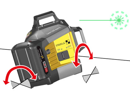
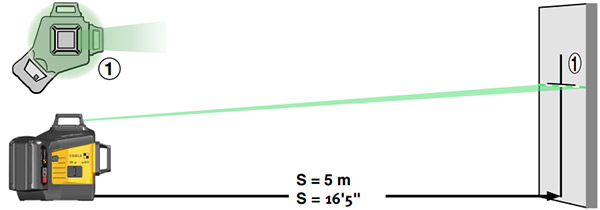
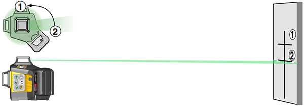
8.2 Kiểm tra phương ngang
Kiểm tra mức độ cân bằng của tia laser ngang Hãy đảm bảo rằng bạn tuân thủ chặt chẽ cách định hướng thiết bị theo hình minh họa được cung cấp.

 |
|
8.3 Kiểm tra góc
Kiểm tra góc 90°
- Đánh dấu điểm A trên sàn, cách 10 m (32'10") trong một góc đủ rộng của phòng.
- Căn chỉnh máy LAX 600 (tia đỏ) hoặc LAX 600G (tia xanh) với điểm A bằng cách sử dụng tia dọi đứng.
- Căn chỉnh máy theo một bức tường bằng cách sử dụng tia laser.
- Đánh dấu chính xác điểm B trên sàn tại vị trí giữa đoạn đường thẳng.
- Đánh dấu chính xác điểm C trên tường hoặc sàn.
- Di chuyển máy và căn chỉnh với điểm B bằng tia dọi đứng.
- Tiếp tục căn chỉnh máy với điểm C bằng tia laser.
- Đánh dấu chính xác điểm D trên tường khác hoặc trên sàn bằng tia laser góc 90°.
Lưu ý:
Khoảng cách từ A đến B, B đến C, và B đến D cần phải bằng nhau để đảm bảo độ chính xác.
- Xoay máy LAX 600 (tia đỏ) hoặc LAX 600G (tia xanh) một góc 90° và căn chỉnh tia laser đầu tiên với điểm D.
- Đánh dấu vị trí E trên tia laser thứ hai vuông góc, càng gần điểm A càng tốt.
- Đo khoảng cách giữa điểm A và E.
 |
 |
 |
||||
 |
 |
|
9. Thông số kỹ thuật
- Loại laser:
- LAX 600: Laser diode tia đỏ, bước sóng 635 nm
- LAX 600G: Laser diode tia xanh, bước sóng 510–530 nm
- Công suất phát: < 1 mW, laser class 2 theo tiêu chuẩn IEC 60825-1:2014
- Phạm vi tự cân bằng: xấp xỉ ± 4°
- *Độ chính xác khi cân bằng:
- Tia laser: ±0,3 mm/m (± 3/16" trên 50ft từ tâm tia laser)
- Góc 90°: ±0,3 mm/m (± 3/16" trên 50ft)
- Pin:
- Pin Li-ion CAS 12 V 2 Ah
- Pin Li-ion CAS 12 V 4 Ah
- Thời gian sử dụng pin:
- LAX 600: ≤ 28 giờ
- LAX 600G: ≤ 15 giờ
- Nhiệt độ hoạt động: -10°C đến +40°C / 14°F đến 104°F
- Nhiệt độ bảo quản: -20°C đến +63°C / -4°F đến 145°F
(Lưu ý: Có thể thay đổi kỹ thuật. *Độ chính xác đảm bảo khi thiết bị được sử dụng trong phạm vi nhiệt độ hoạt động quy định.)
Bài cùng nhóm Hướng dẫn sử dụng
 HDSD bộ nhân lực cơ khí alkitronic M-ML 4:1
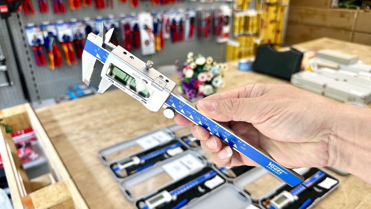 HDSD Thước kẹp điện tử 150 mm Vogel Germany 202043-3
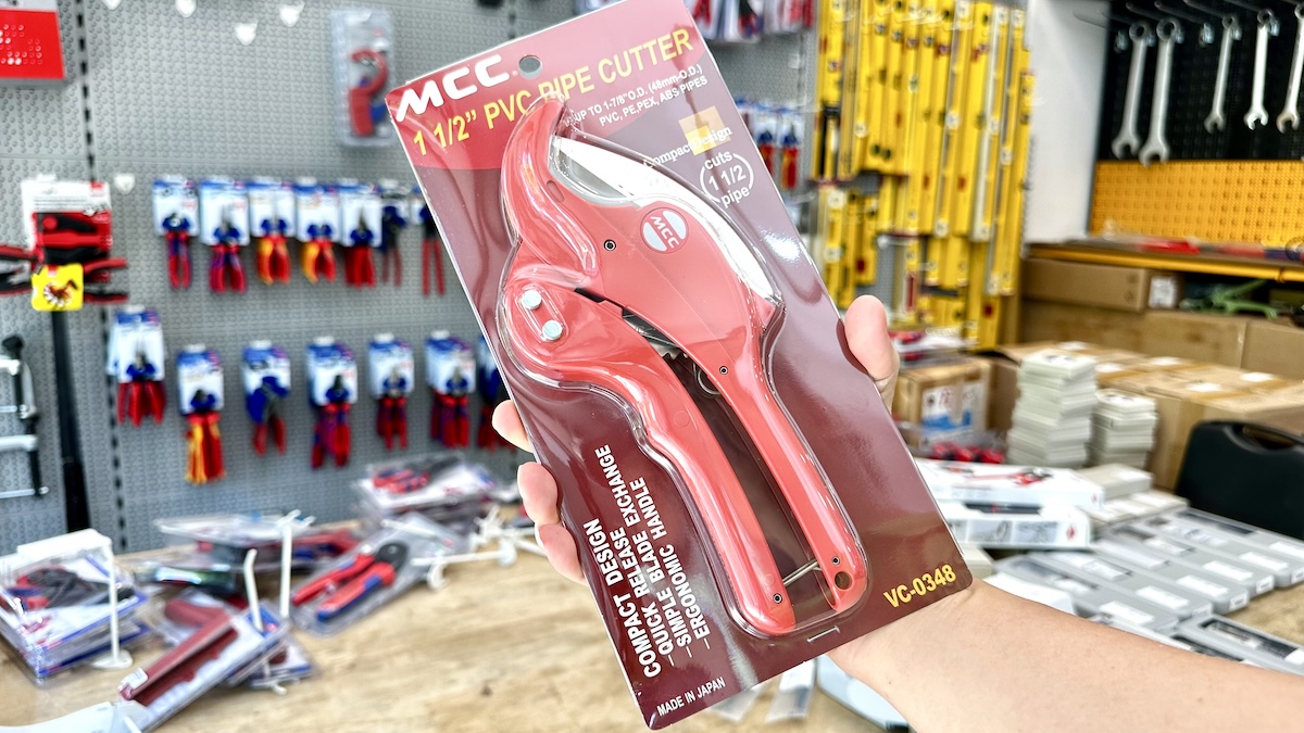 Hướng dẫn sử dụng kéo cắt ống nhựa MCC VC-0348
 Vận hành nhiều máy phát MF-Generator ở chế độ mạng LAN
 Số vòng quấn tối ưu của cuộn cảm linh hoạt MF Gernerator
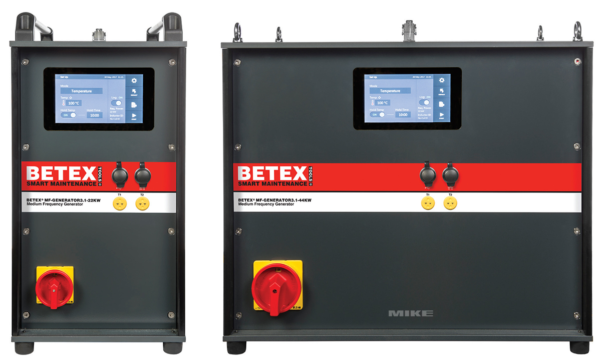 Hướng dẫn sử dụng BETEX MF-GENERATOR3.1, máy gia nhiệt quấn dây
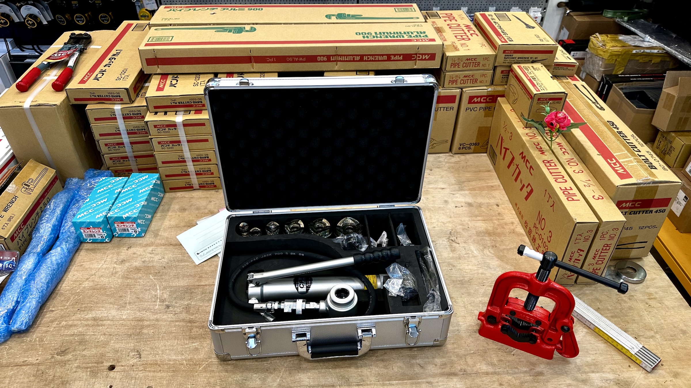 Bộ đột lỗ thủy lực SKP, Cactus MCC Japan, hướng dẫn sử dụng.
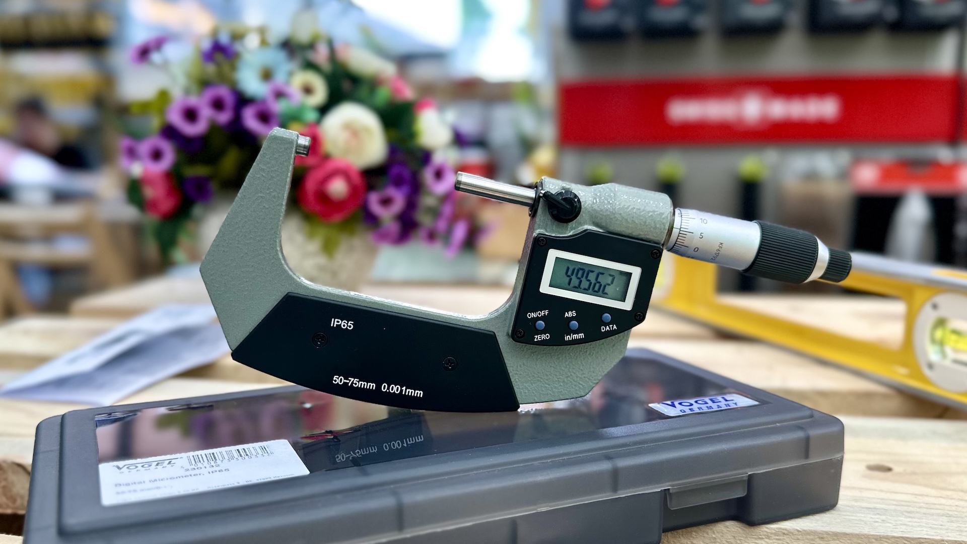 Hướng dẫn sử dụng thước panme điện tử Vogel Germany
Bài khác bạn có thể quan tâm
 QA kiểm thử ERP cho dự án xây dựng hệ thống quản trị nội bộ.
 Lập trình frontend ERP cho dự án xây dựng hệ thống quản trị
 Lập trình backend ERP cho dự án xây dựng hệ thống quản trị
 Kiến trúc sư hệ thống ERP dự án xây dựng hệ thống quản trị nội bộ
 Business analyst ERP dự án xây dựng hệ thống quản trị nội bộ.
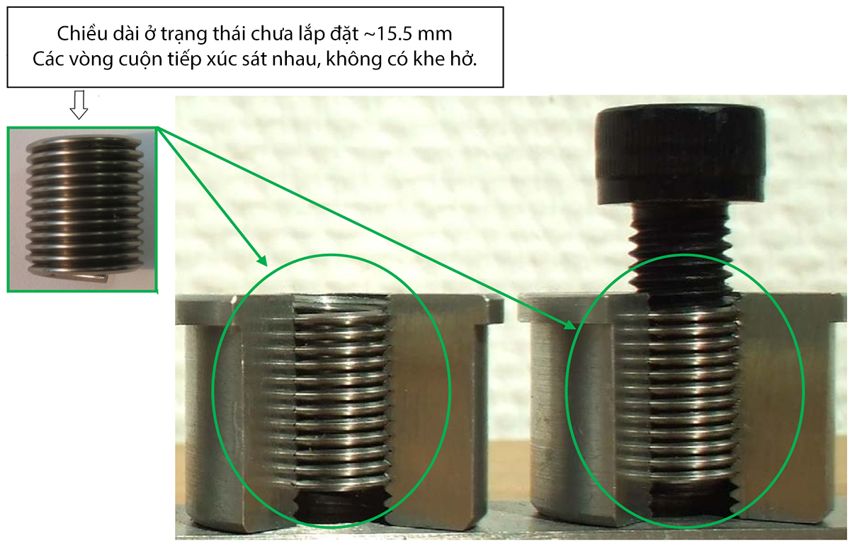 Hiểu đúng về chiều dài của vòng ren dây V-COIL
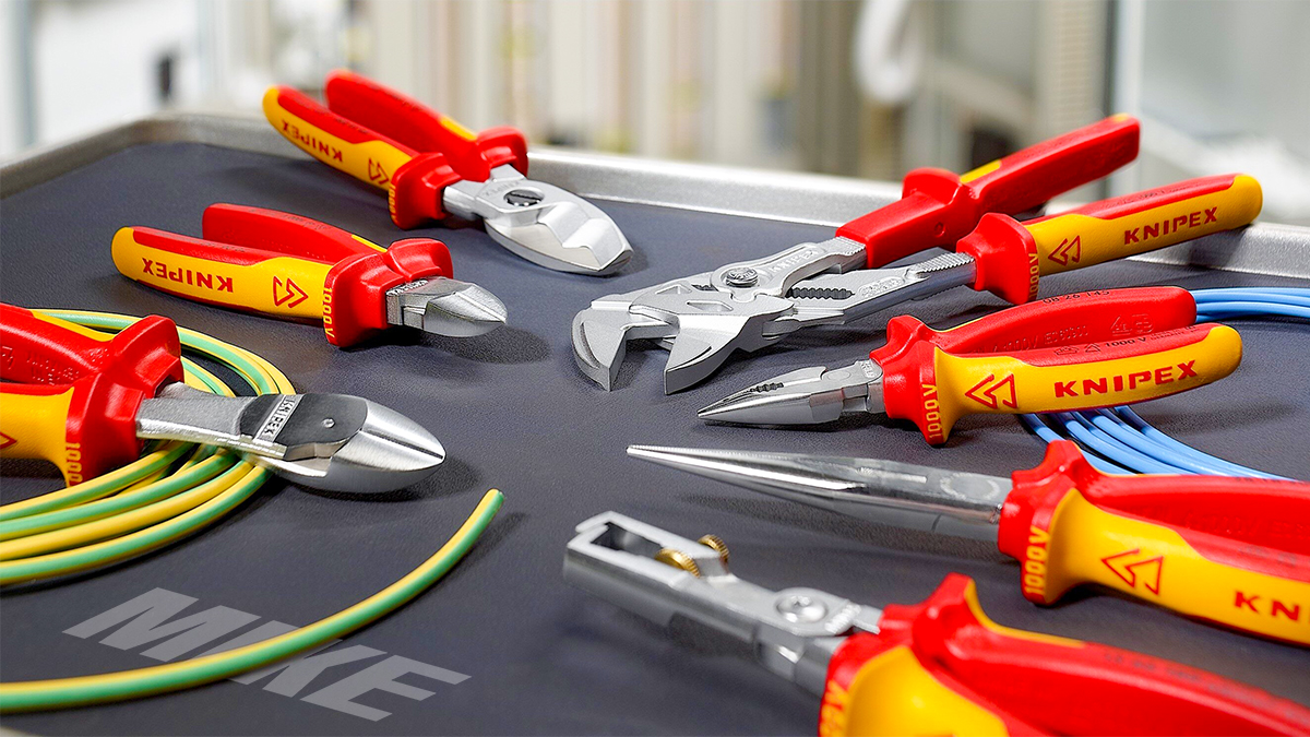 Dụng cụ đồ nghề cách điện VDE 1000V - Made in Germany
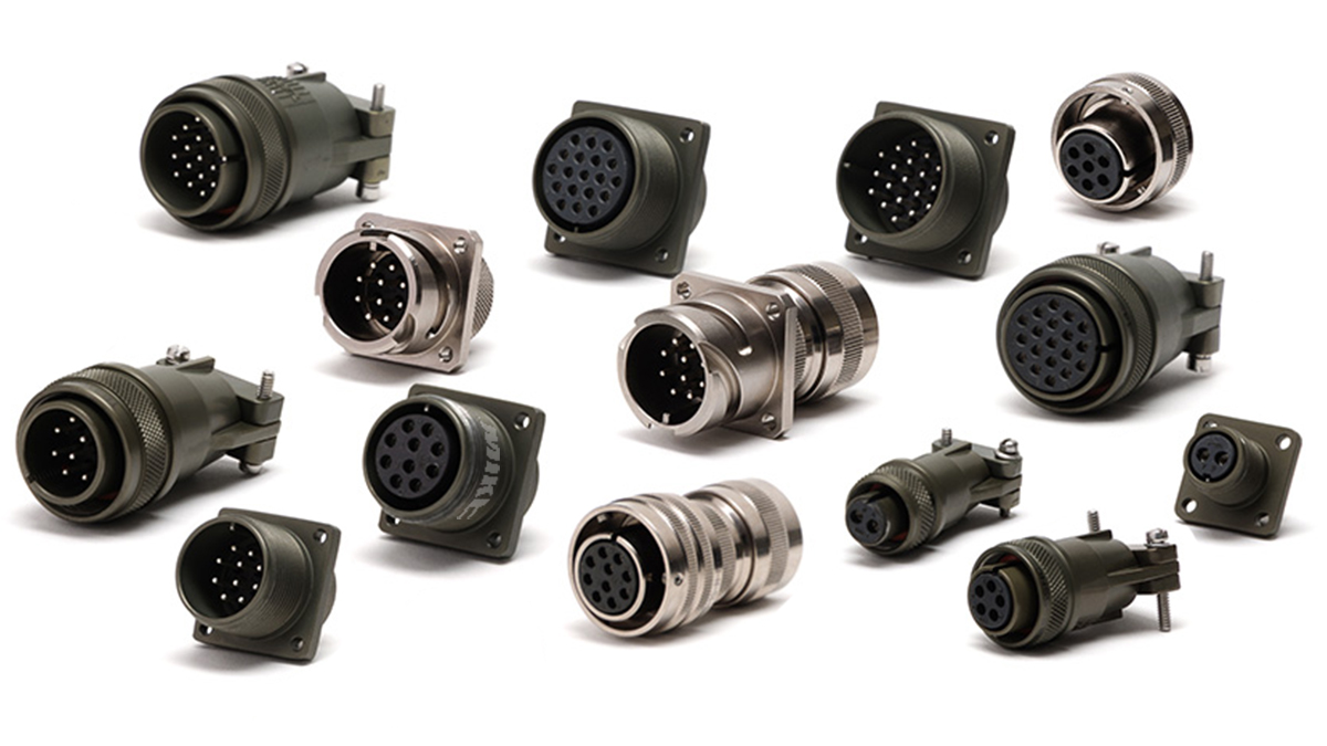 Cos circular connector trong ngành hàng không là gì?